


How-To's
Contents
- Dual power supply modification
- Flashing firmware
- Dedicated AVR programmer
- Arduino
- Raspberry Pi
- USB-serial port converter based on FTDI chip
- Parallel port
- Cloning password-protected NTAG213 and EV1 tags
WARNING
Some information in this section could be used in a way that could result in void warranty. The user is ultimately responsible for all modifications of Emutag. All hardware modifications and firmware reflashing void warranty. Please use this information with understanding of what exactly you are doing. Read everything first, then modify or reflash!
Dual power supply modification
If Emutag has to work next to NFC reader for extended periods of time, it is strongly recommended to use external 5V DC power. Unless reflashed with new firmware with LVR patch, failing to do so might result in corrupted firmware due to running at high clock speed at low battery voltage, which is not monitored by BOR (brown-out reset) in order to prevent draining 20 µA of current when NFC reader field is not present. The phenomenon of firmware corruption is described in ATtiny4313 datasheet on pages 20 and 176. The minimum safe operating voltage is calculated from the speed grade for 13.56 MHz frequency:
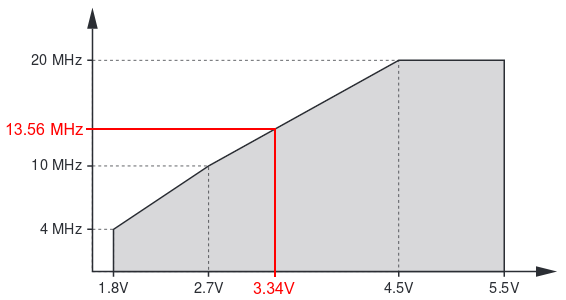
Please note that battery voltage under load is much less than with no load, so simply measuring battery voltage when Emutag is not in NFC reader field is not representative!
If external power is not always available and tag data needs to be preserved without external power, the following schematic concept with 2 diodes can be used to automatically select the power source, wherever the voltage is higher:
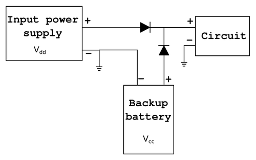
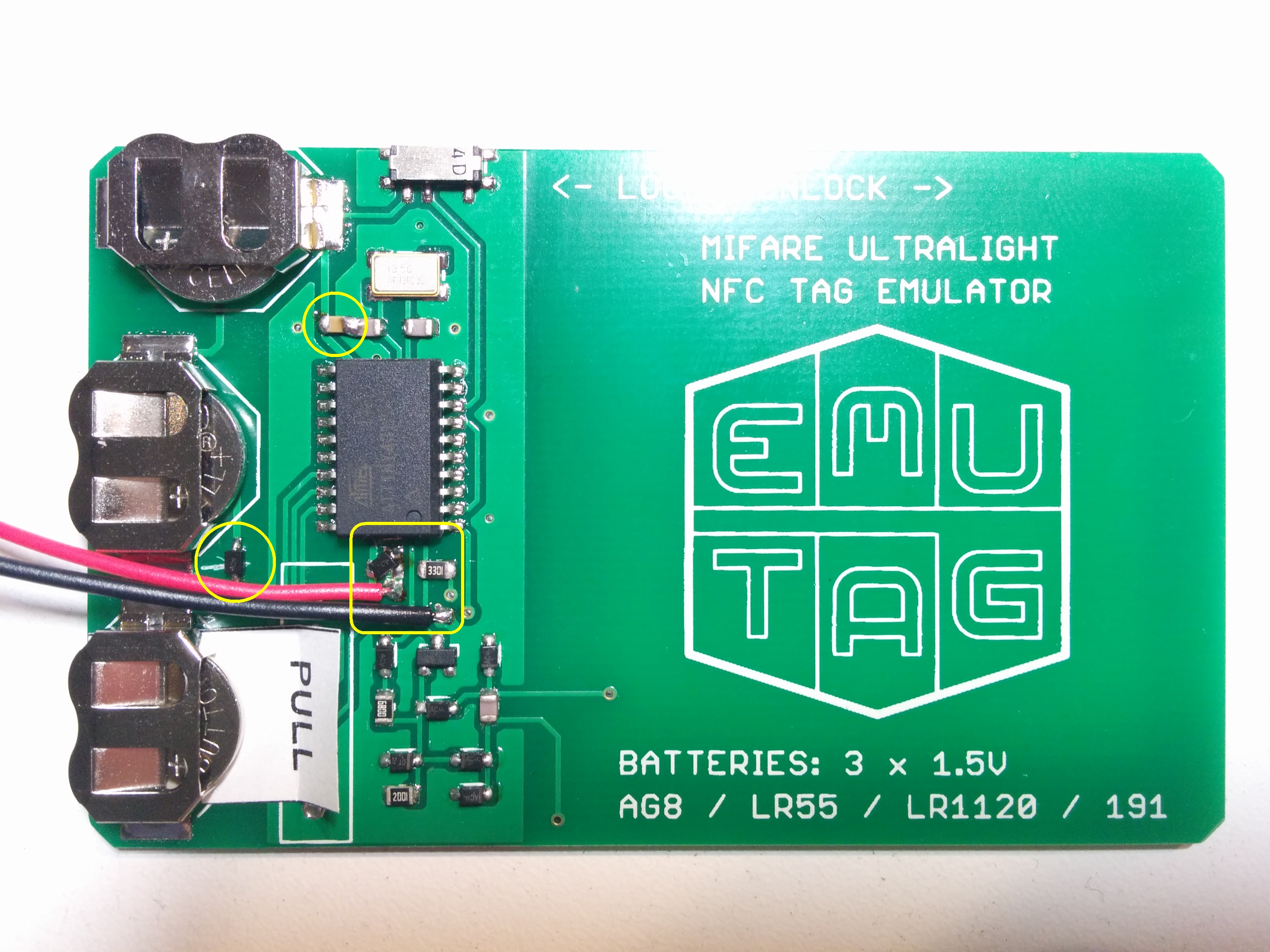
The above circuit can be implemented on Emutag as shown in 3 next images (click to view full size).
 |
 |
 |
||
Final view |
PCB modifications |
Part modifications |
If firmware corruption has already occured, the next section describes how to reflash Emutag.
Flashing firmware
So far, 5 methods are known to work to successfully reflash (overwrite firmware in) Emutag:
- Dedicated AVR programmer
- Arduino
- Raspberry Pi
- USB-serial port converter based on FTDI chip
- Parallel port
Hardware connections
The pinout of Emutag's ICSP connector is provided here:
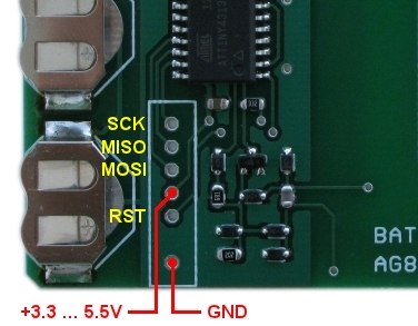
A dedicated AVR programmer should have programming pins with same names. Other programming hardware should be connected according to this table:
| EMUTAG | Arduino Uno | Arduino Mega | Arduino Nano | Raspberry Pi | FTDI chip | Parallel port |
|---|---|---|---|---|---|---|
| SCK | 13 | 52 | D13 | 21 | CTS | 8 |
| MISO | 12 | 50 | D12 | 16 | RXI | 10 |
| MOSI | 11 | 51 | D11 | 20 | TXO | 9 |
| VCC | 5V | 5V | 5V | 5V | VCC | 2, 3, 4, 5 |
| RST | 10 | 53 | D10 | 12 | DTR | 7 |
| GND | GND | GND | GND | GND | GND | 18 - 25 |
Use only FTDI adapters that have 3.3V or 5V logic level output. Never connect directly to a 12V standard serial port!
Add series resistors of 220Ω on each pin of parallel port to protect it, especially pins 2-5, in case they drive different logic levels at the moment of connecting the programmer, which shorts them!
Firmware files
Update:
In February 2019 new firmware files have been released with the LVR patch, and flashing commands have been updated with values highlighted in red.
Depending on the type of NFC tag that needs to be emulated, you need to download the corresponding Flash memory image file:
And the EEPROM image file, common for all firmwares. You can also check out the entire firmware directory for other less popular NFC tags and older firmware versions.Software instructions
Windows users: if you are using avrdude from WinAVR-20100110, it does not support ATtiny4313 by default. To patch this, you need to download additional ATtiny4313 configuration, copy all the code from it, and paste into the file <WinAVR>\bin\avrdude.conf after the description of ATtiny2313 (by default at line 8918).
The software procedure is specific to each of the 5 programming methods, so each will be described separately. In the following instructions for different hardware, NTAG213 firmware file will be used as example. Replace it with the file for your firmware version.
Dedicated AVR programmer
Programmers for use with avrdude: configure the programmer type, optional serial or USB port, baud rate, and run the following flashing command from the directory with 2 downloaded firmware files:
See avrdude manual for more information.
Non avrdude-based programmers: specify binary file format for both Flash and EEPROM images, and configure fuses accoring to the following table:| Bit | Extended fuse byte | High fuse byte | Low fuse byte | |||
|---|---|---|---|---|---|---|
| 7 | - | 1 | DWEN | 1 | CKDIV8 | 1 |
| 6 | - | 1 | EESAVE | 1 | CKOUT | 1 |
| 5 | - | 1 | SPIEN | 0 | SUT1 | 0 |
| 4 | - | 1 | WDTON | 1 | SUT0 | 1 |
| 3 | - | 1 | BODLEVEL2 | 1 | CKSEL3 | 1 |
| 2 | - | 1 | BODLEVEL1 | 0 | CKSEL2 | 1 |
| 1 | - | 1 | BODLEVEL0 | 1 | CKSEL1 | 1 |
| 0 | SELFPRGEN | 0 | RSTDISBL | 1 | CKSEL0 | 1 |
Arduino
Open Arduino IDE. Select from the menu Tools => Programmer => Arduino as ISP. Upload the code to Arduino as you normally upload any other code.
Then take a wire and short RESET and 5V pins on the Arduino, in order to prevent the Arduino itself from entering its own bootloader. Never press the RESET button manually while the wire is in place, as that would short the USB supply!
Run the following flashing command from the directory with 2 downloaded firmware files:
The port is the same as you select in Arduino IDE for interfacing it. It is recommended not to update fuses when flashing from Arduino, in order to prevent bricking Arduino with incorrect fuse settings if something goes wrong.
Raspberry Pi
Make sure Raspberry Pi is connected to the Internet. In Raspberry Pi's terminal, run the following commands:
sudo nano /etc/avrdude.conf
Somewhere in the file find the commented out "linuxgpio" section and add this code in there:
id = "linuxgpio";
desc = "Use the Linux sysfs interface to bitbang GPIO lines";
type = "linuxgpio";
reset = 12;
sck = 21;
mosi = 20;
miso = 16;
;
Save the file and exit by pressing Ctrl+X, then Y. Then download the firmware files on Raspberry Pi and flash:
wget http://emutag.com/firmware/common.eep
sudo avrdude -c linuxgpio -p t4313 -U flash:w:ntag213-LVRpatch.bin:r -U eeprom:w:common.eep:r -U efuse:w:0xFE:m -U hfuse:w:0xDB:m -U lfuse:w:0xDF:m
* These instructions are described in more detail in this blog.
FTDI chip (tested on Windows only)
* To do this on Linux, please follow this link.
Download a modified version of avrdude with FTDI bitbang patch and place the two downloaded files into the same directory with the firmware files:
Check the pinout of your specific FTDI adapter, and if necessary, modify the pinout in the downloaded file "avrdude.conf" starting from line 465 (SparkFun FTDI Basic breakout). This file "avrdude.conf" is already patched to include ATtiny4313 chip. Then flash by running the following command from the directory of the downloaded files:
If the programmer is unable to recognize the chip, try writing the low fuse only at a lower speed first, and then the full command. The low fuse is programmed with this command:
Parallel port (tested on Linux only)
Windows versions starting from 2000 have implemented a kernel-mode driver that interferes with user-mode parallel port operation even if a user-mode driver is setup for accessing the port. For that reason, programming with parallel port on Windows is unreliable and depends on specific machine hardware. Linux offers a much more stable way of flashing Atmel chips through the parallel port.
If you don't have Linux installed, you can launch it without installing by booting from a live CD or DVD or USB. Once booted, connect to the Internet. Then run the following commands in a terminal:
wget http://emutag.com/firmware/ntag213-LVRpatch.bin
wget http://emutag.com/firmware/common.eep
sudo avrdude -c bsd -P /dev/parport0 -p t4313 -U flash:w:ntag213-LVRpatch.bin:r -U eeprom:w:common.eep:r -U efuse:w:0xFE:m -U hfuse:w:0xDB:m -U lfuse:w:0xDF:m
If the last flashing command gives an error saying /dev/parport0 cannot be found, load the parallel port kernel driver and repeat the flashing command again. Parallel port kernel driver is loaded with this command:
Cloning password-protected NTAG213 and EV1 tags
- Read NFC counter(s):
- NTAG213: send command 39 02 and record the value decremented by 1. If you get NAK, means NFC counter is disabled.
- EV1: read all counters with commands 39 00, 39 01, 39 02 and record read values as is.
- Read all readable pages off the original tag.
- Read signature with command 3C 00.
- Set switch on Emutag to Unlocked mode.
- Load pages on Emutag with command A2 followed by page number and 4 data bytes.
- If signature needs to be cloned, send 8 WRITE commands to pages 46-53 in a single session, with 4 data bytes per command (total 32 bytes). Multiple commands are sent by entering each command on a new line in NFC Shell.
- If page containing ACCESS byte could not be read at step 2, write 80050000 to that page and 040000XX to the previous page, where XX is the number of the first page that could not be read. This will make unreadable pages on the original tag also be unreadable on the Emulator.
- Write 000000E0 to page 45 to enable Timeout sniffing mode.
- Write counters: 3 bytes of the counter go to bytes 0-2 and byte 3 is 00.
- NTAG213: if NFC counter is enabled, write the previously recorded value to page 45.
- EV1: write previously recorded values to pages 43, 44, 45 for counters 0, 1, 2 respectively.
- Move the switch to Locked position.
- Scan Emutag on the reader that expects the original tag. If the reader sent the password, the transacton should fail with timeout. Remove Emutag from the reader after a few seconds.
- Move the switch to Unlocked mode.
- Read the PASSWORD page off Emutag. It's the password.
- Send AUTH command to the original tag using the sniffed password: 1Bxxxxxxxx, where xxxxxxxx is the password.
- The reply you should get is the PACK code, write it to first 2 bytes of PACK page of Emutag.
- Send AUTH command to the original tag again, followed by READ commands of all remaining pages in a single session, or a single FAST_READ command with correct arguments.
- Write the remaining pages to Emutag.
- Disable sniffing mode by writing 000000F0 to page 45.
- For NTAG213 only, write NFC counter again with previously recorded value, as described in step 9.
- Move the switch to Locked mode, and Emutag is now ready to replace the original tag.